3D Graphics, Tutorials and Tips
Using 3DS Studio Max and Mental Ray


3D Graphics, Tutorials and Tips
Using 3DS Studio Max and Mental Ray


Dr. Who's arch-nemesis, the Dalek as classic Genesis and New Series versions
H.M.S. Nelson, big gunned capital warship from WWII
Edwardian house. Old school architectural renderings
Assorted models and renders
These tutorials focus on using the Mental Ray renderer (iRay tutorials in preparation). The production shaders enable the easy integration of 3d Models into photographs.
These renders have been created to visualise scientific concepts and experimental layouts. A 10 minute HD film was also created.
Geological Waste Disposal Bluray/HD 2009
Geological Waste Disposal DVD 2003
PSG Experiment - Grimsel (Nagra)
Rendering and compositing of 3D models for international Clients
Front cover for Burton Power Catalogue 2012
Front cover for Burton Power Catalogue 2014
Front cover for Burton Power Catalogue 2015
Front cover for Burton Power Catalogue 2016
Wavemaster Design : Ferry design renders
Car Colour Services : Colour and spraying services
Volkswagen Crafter for Volkswagen Australia
DMMultimedia | 3d tutorials | Classic RS Alloy
What I will outline here is the method I used to create my 13" RS RS3100 alloys. This is not the only approach - but for 4 or more symmetrically spoked wheels it is quite useful. It is not intended that this is a step-by-step guide, more to show the methodology of my approach. You can follow along in more detail in the BBS Alloy wheel tutorial
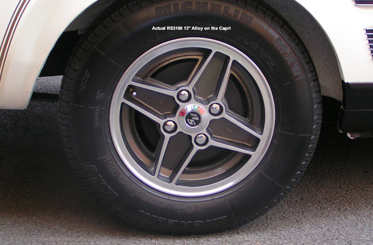
Firstly starting with the wheel, I had an original copy. The more reference pics the BETTER !
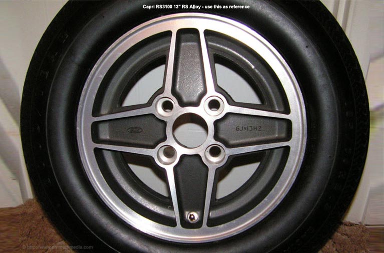
But I was lucky enough to get a pic of the wheel almost straight on, and it is this pic that I will use as my guide:
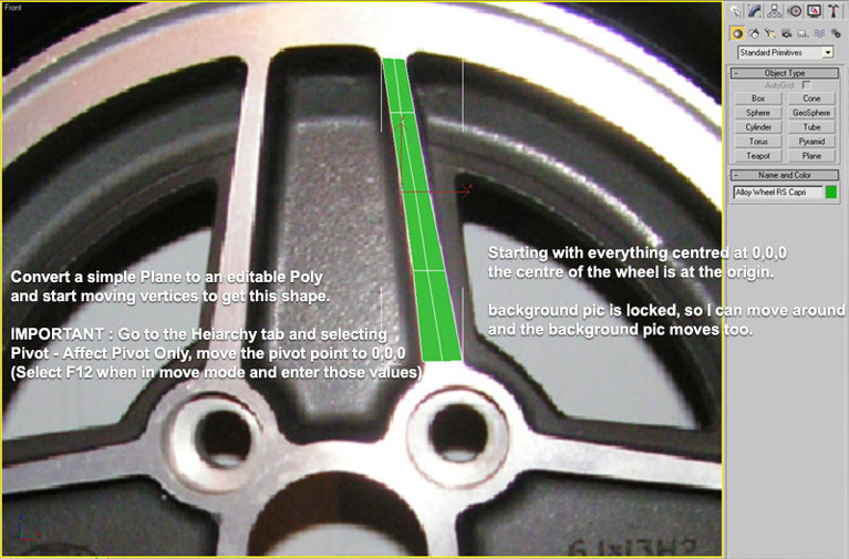
Make as sure as you can that the centre of the wheel in the pic is in the actual centre of the Pic - Use Photoshop guidelines to position the wheel in the centre of the pic. Now, starting MAX I load a cropped version of the above pic into the Views - Viewport Background (no need for this pic to be huge, it only needs to be at least as big as your viewport). Make sure you Lock Zoom/Pan - This means that the PIC will be locked with its centre at 0,0,0 and we can zoom and move around and the pic will follow - VERY HELPFUL !!
With the background loaded and Lock Zoom/Pan on, we can zoom in a little on one of the spokes. I created a simple pane object with a few sections and converted this to an Editable Poly - moving the vertices to get the pic below. IMPORTANT : At this point go to the Hierarchy Tab and select Pivot - Affect Pivot Only and with the move tool selected press F12 and enter 0,0,0 for the positron. This means that the centre of rotation for our Patch is around the centre of the wheel - we NEED this for later.
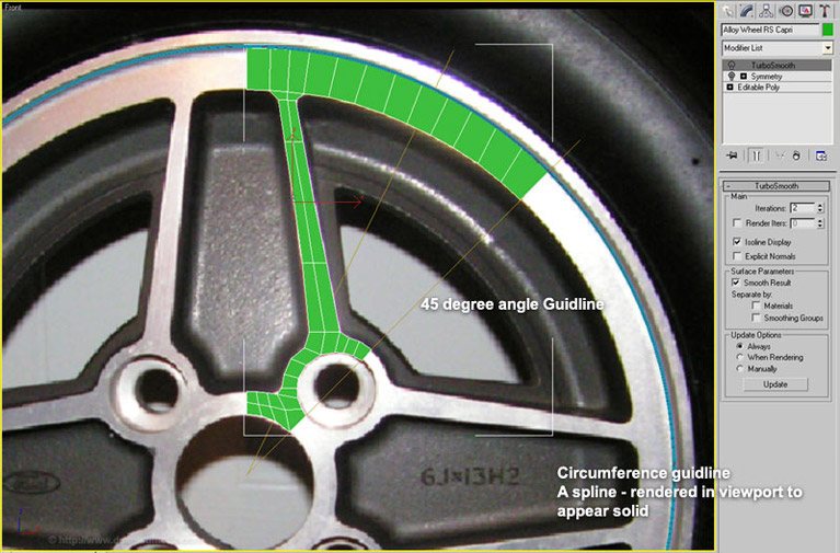
Now another important part, as I am modelling a quarter of the wheel I know it will occupy 90 degrees of rotation. So that I know where to model to, I have the centre line (straight up and down at 0,0,0) but I have also added a 45 degree line to show the boundary of my segment. I do not need to model outside that guide. (with more spokes this angle will be lower)
I have also added a few circular guides (again centred at 0,0,0) for the outer rim of the alloy. I ticked render in viewport to make them very clearly visible.
Thinking a little ahead try and make your quads regular, and control the size of them to control any curves. Try to keep any lines that point from the centre line in a radial way (like a star). See how the edge that runs along the 45 degree guideline ?
Apply a Symmetry modifier on the shape. One tip is to make sure that ALL the vertices lying along the join line should be exactly at x=0 - so that they will weld nice and smoothly. This will now give us:
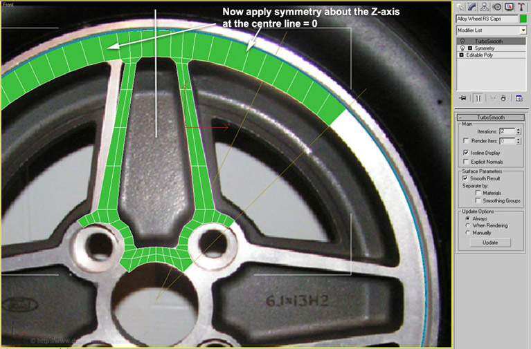
Don't worry that it doesn't line up with the background image - as long as it fits with our circular guides !
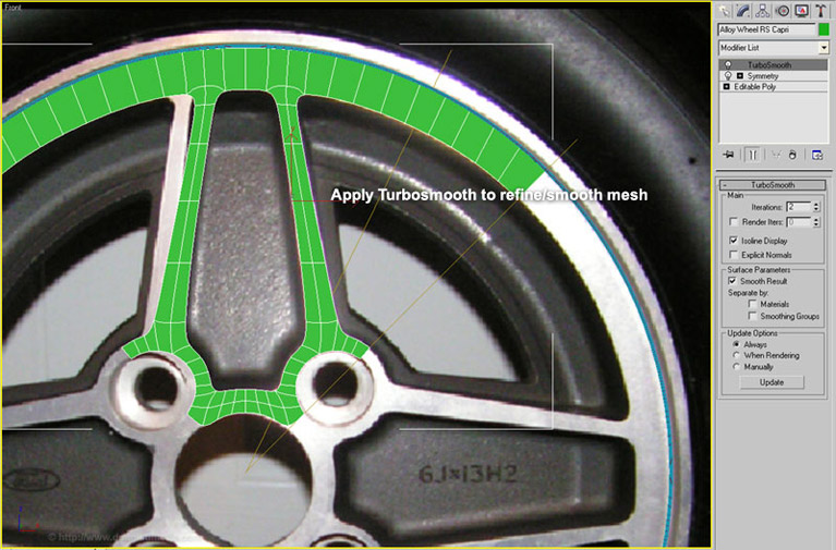
And we can add a Turbosmooth modifier to that :
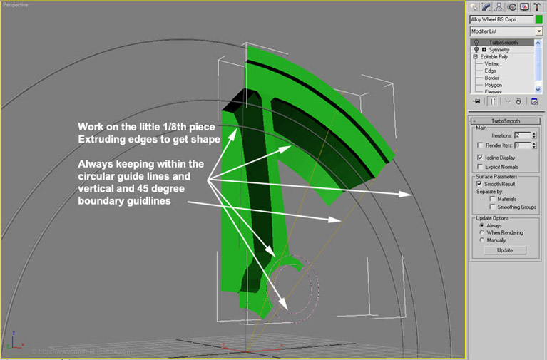
Switch off the Turbosmooth and Symmetry. We can continue to model, using edge extrude, moving vertices etc. You can see that I used some circular guides for the bolt holes with the centre of those circular guides lying on the 45 degree guideline :
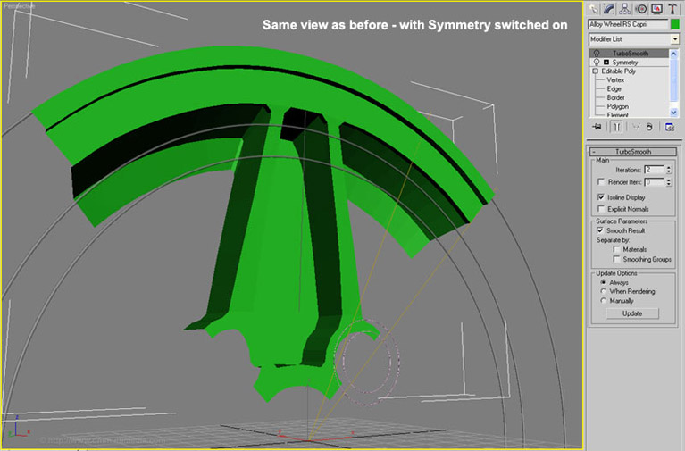
And with the Symmetry modifier back on :
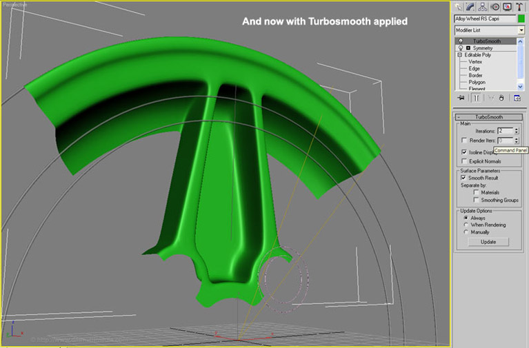
And with Symmetry and Turbosmooth modifiers on :
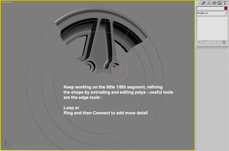
Switch the Symmetry and Turbosmooth modifiers off and continue to refine the shape - try and put as much effort into this part - it is MUCH EASIER to add the detail here than when we join the wheel - YOU HAVE BEEN WARNED ! At the very least save many versions as you progress.
I refined the shape to this :
Save your Scene before doing this step ! So that you can go back and change anything.
Delete Turbosmooth from and Collapse All in the Modifier Stack.
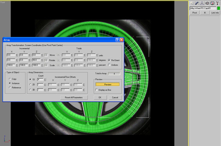
Selecting the Front view, select Tools - Array. Then use the following values, rotating about the Z axis in 90 degree increments a total of 4 times, Instances and Show Preview :
Now, because your other spokes are instances any last minute adjusting of the shape need only be done on one 1/4 segment and it will be adjusted on them all.
I got this :
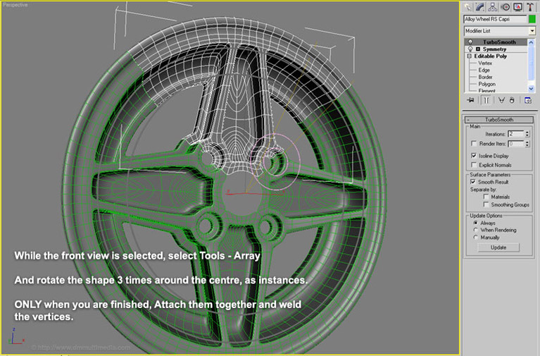
Now all that remains is to Attach the segments to each other and weld the vertices - this can be done manually to make sure, or you can select the join lines and Weld Vertices (using the tolerance settings on the tool to restrict what gets joined together).
I actually did an Array to just 2 parts (a half wheel) and joined them together by hand because I had some closely chamfered edges that I wanted to be sure were correctly welded - then Array that half one more time. just to minimise the amount of times I welded vertices
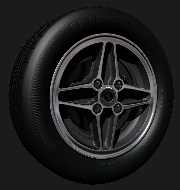
With the wheel finished add some bolts, RS wheel cap, tyre and textures :