
3D Graphics, Tutorials and Tips
Using 3DS Studio Max and Mental Ray


3D Graphics, Tutorials and Tips
Using 3DS Studio Max and Mental Ray


Dr. Who's arch-nemesis, the Dalek as classic Genesis and New Series versions
H.M.S. Nelson, big gunned capital warship from WWII
Edwardian house. Old school architectural renderings
Assorted models and renders
These tutorials focus on using the Mental Ray renderer (iRay tutorials in preparation). The production shaders enable the easy integration of 3d Models into photographs.
These renders have been created to visualise scientific concepts and experimental layouts. A 10 minute HD film was also created.
Geological Waste Disposal Bluray/HD 2009
Geological Waste Disposal DVD 2003
PSG Experiment - Grimsel (Nagra)
Rendering and compositing of 3D models for international Clients
Front cover for Burton Power Catalogue 2012
Front cover for Burton Power Catalogue 2014
Front cover for Burton Power Catalogue 2015
Front cover for Burton Power Catalogue 2016
Wavemaster Design : Ferry design renders
Car Colour Services : Colour and spraying services
Volkswagen Crafter for Volkswagen Australia
DMMultimedia | 3d tutorials | Simple Tyre Tutorial | Modelling the tread


Part 1. Modelling the the tyre tread
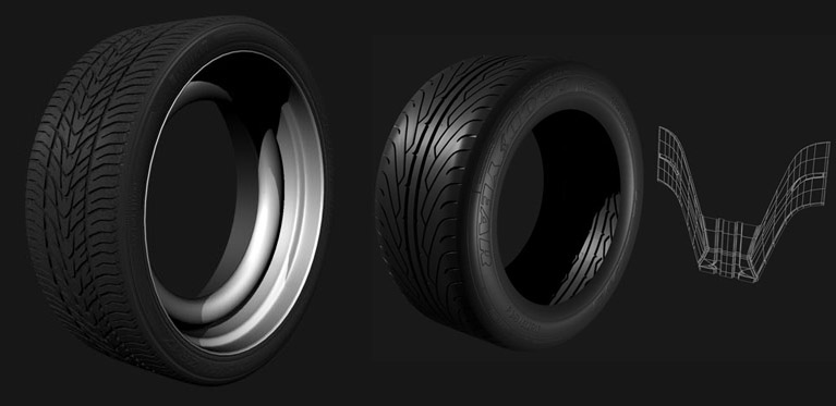
This tutorial shows a "quick & dirty" method of creating Tyres using a "low poly" mesh.
It is not meant to be the most detailed or accurate method (there are other tutorials on the internet that outline detailed tyre creation with all the little subtle bumps and indents - excellent for closeups) but the method outlined here will create a tyre that will be more than realistic enough for most shots - but using a LOT less polys than a Mesh/Turbosmoothed mesh.
The same method, of creating a small repeating pattern and applying symmetry can be used for almost any tyre - alternative pattern was used to create the tyre n the right below:
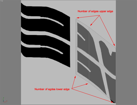
First step is to select a tyre and find the repeating pattern. In this example I have already selected the repeating pattern (From a bitmap supplied by BrokenBone ). You can download the JPEG here 48kb. A preview is shown below, background colour is a neutral grey which contrasts with the white edges of an object so we can see them more clearly:

Load this into the top viewport background. Create a plane and convert it to an Editable Poly. Use shift - extrude on edges, ring and connect etc., to add more refinement/shape to the mesh. This does not have to be very accurate - although you can make this as refined as you want. IMPORTANT : Make sure that the number of edges/vertices on the top edge and bottom edge (as seen below) are exactly the same amount - this is needed later for joining copies.
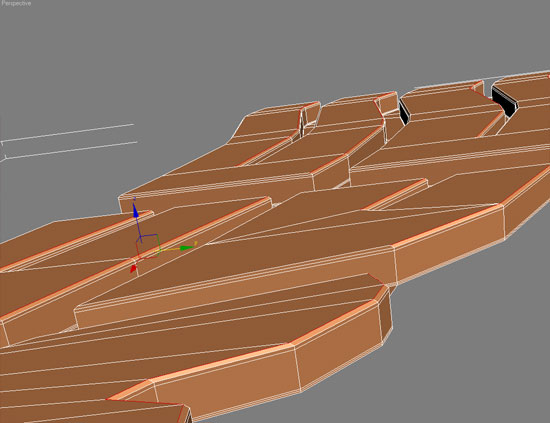
Keep creating new edges (by holding shift as you drag out a new edge, or ring and connect) and build up an approximate shape. Once you have a basic shape select all the tread blocks.
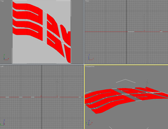
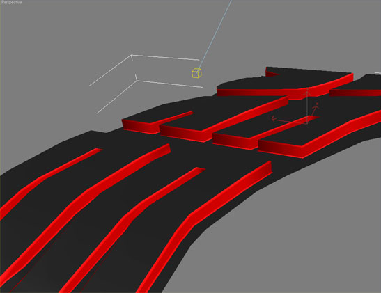
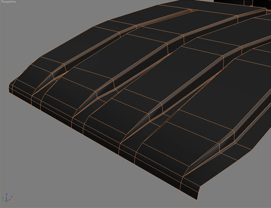
With the tread block polys selected use the extrude tool to create several levels to the newly extruded blocks.

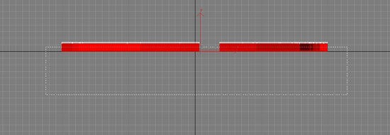
Now comes a little work. More work here will result in a more realistic tyre later. We will move some of the vertices to add a little bevel where the tyre blocks join the tyre and at the tops of the tyre blocks. These will catch the light with smooth edges and look much more realistic.
To do this select all the upper edges facing in one direction as seen above, then move them as shown below.
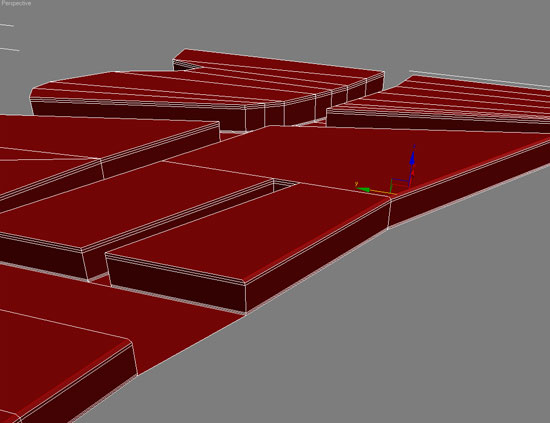
Repeat this process for all the upper tyre block edges and also the same effect (but moving out) for the edges where the tyre block joins the tyre. The image below is in the middle of this process.
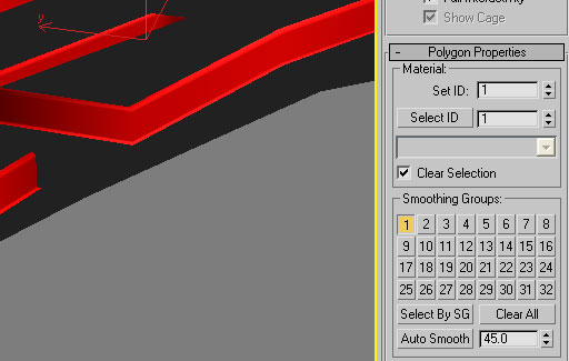
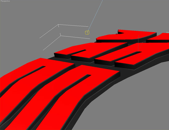
Keep adjusting edges to get a nice bevel around the tyre blocks. After this has been done we will assign smoothing groups to this object. We want 3 smoothing groups :
It is easier to select all the polys we need from a side view, selecting large areas then grow/shrink - or select inverse to get the areas we want. Holding Ctrl will select multiple polys, while holding Alt will subtract polys from a selection:
Select large areas of polys and assign a SEPARATE smoothing group to each selection (1,2,3). It is not important what smoothing group number you use, but make sure that all the smoothing groups have a SEPARATE number for each selection of polys.
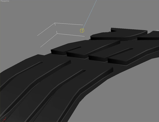
Do this for all three groups, each with a separate smoothing group:
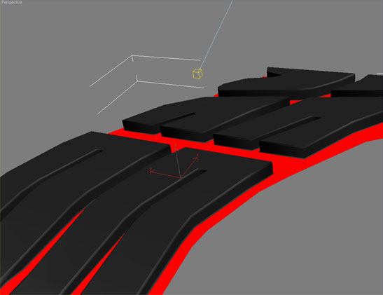
This will now give us a nice bevel to the tyre with smoothing (without adding extra polys when using Mesh/Turbosmooth). The bevels catch the light nicely.
One other point to note, which will make life easier later is to adjust the edge of the tyre that flows onto the tyre side wall (which we will create later). At the moment in this example that edge is irregular - if we select one edge and then loop it will not select the whole edge. Select all the edges by hand and shift extrude a new set of edges (two sets have been added below. This set of edges can now be selected using loop.
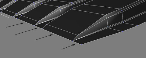
As can be seen in the above image it is not necessary to use only 4-sided polys as we will not be using Mesh/Turbosmooth, so we have the flexibility to use low poly techniques to keep poly count down.


